Sep. 02, 2026

KBP and GBP are compact, single-phase bridge rectifier packages used to convert AC input into full-wave rectified DC. They have similar body dimensions and are available with many matching current and reverse-voltage ratings. Their main differences are mechanical: lead shape, lead length, polarity identification, and suitability for automated assembly.
KBP generally uses round wire leads, with one longer lead identifying the positive (+) terminal. GBP uses flat, equal-length leads formed from a lead-frame structure. This design provides more defined positioning, better resistance to rotation, and a more consistent mounting height.
Feature | KBP | GBP |
Rectifier type | Single-phase full-wave bridge | Single-phase full-wave bridge |
Lead shape | Round wire leads | Flat stamped leads |
Lead length | One longer positive lead | Four equal-length leads |
Positive-terminal identification | Longer lead, chamfered corner, and + marking | Chamfered corner and + marking |
Representative body size | Approx. 14.5 × 11 × 3.7 mm | Approx. 14 × 10.5 × 3 mm |
Common current classes | 2 A and 3 A | 2 A, 3 A, 4 A, and 6 A |
Common voltage classes | 400–1000 V | 400–1000 V |
Typical assembly fit | Manual and conventional through-hole insertion | Through-hole insertion with added automation advantages |
Dimensions and ratings vary by manufacturer and series. Always confirm the approved drawing and datasheet before PCB design or replacement approval.
KBP: round leads
KBP packages normally use four round wire leads. They fit naturally into standard round PCB holes and are convenient for manual insertion, prototyping, and conventional through-hole production.
One lead is typically longer than the other three. In the KBP configuration discussed here, this is the positive (+) lead. The longer lead gives operators a clear visual and tactile orientation reference before insertion.
Because round leads can rotate inside PCB holes before soldering, the assembly process may require additional orientation control. Unequal lead length can also make uniform insertion depth more difficult in some automated systems.
GBP packages normally use four flat leads formed from a stamped lead frame. Their flat profile provides a defined orientation and helps resist rotation during handling and insertion.
The four equal-length leads support a consistent insertion depth and mounting height. These characteristics can improve repeatability in automated feeding, insertion, and inspection. However, the actual benefit depends on the PCB footprint, feeder, tooling, packaging format, and soldering process.
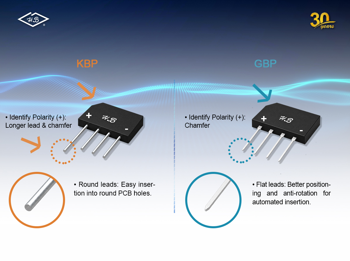
Correct polarity is essential because reversing the DC output can damage downstream capacitors, control ICs, and other polarity-sensitive components.
For a typical KBP, the positive terminal is identified by:
1. the longer positive (+) lead;
2. the chamfered corner; and
3. the printed or molded + marking.
For a typical GBP, all four leads are equal in length. The positive terminal is identified by:
1. the chamfered corner; and
2. the printed or molded + marking.
A chamfered corner is a corner cut at an angle instead of forming a complete 90-degree corner. It provides a permanent mechanical orientation feature.
For concise production instructions:
KBP: Positive (+) — longer lead and chamfered corner
GBP: Positive (+) — chamfered corner
Body markings and the approved datasheet should remain the final reference because special versions or manufacturer conventions may differ.

The representative body dimensions in this comparison are:
KBP: approximately 14.5 × 11 × 3.7 mm
GBP: approximately 14 × 10.5 × 3 mm
GBP therefore provides a similar board area with a slightly slimmer profile in the compared series. Similar body dimensions, however, do not guarantee a direct mechanical replacement.
Before changing from KBP to GBP, verify:
1. lead pitch and pin spacing;
2. round-lead diameter versus flat-lead width and thickness;
3. finished PCB-hole size and plating allowance;
4. body length, width, height, and clearance;
5. insertion depth and final mounting height;
6. polarity orientation relative to the PCB legend; and
7. soldering and lead-forming requirements.
A hole designed for a round KBP lead may require adjustment for a wider flat GBP lead.
KBP and GBP families are available with many comparable current and reverse-voltage ratings. For example, both can be supplied in 2 A or 3 A versions with 600 V, 800 V, or 1000 V ratings. GBP families may also extend to 4 A and 6 A versions.
The key parameters are:
VRRM: peak repetitive reverse voltage.
IF(AV): average rectified output current under specified thermal conditions.
VF: forward voltage at a specified current and temperature. Two diodes normally conduct at the same time in a bridge, so conduction loss is affected by approximately two forward-voltage drops.
IFSM: non-repetitive peak forward surge current, especially important when charging an input capacitor at power-on.
IR: reverse leakage current.
Thermal ratings: junction temperature, thermal resistance, lead conditions, PCB layout, and ambient temperature.
KBP and GBP can have matching headline ratings, but they are not automatically electrically identical. Two 3 A, 1000 V devices may still differ in forward voltage, surge capability, leakage current, thermal limits, or test conditions. Exact datasheets must be compared parameter by parameter.
Many model numbers combine the current class with a voltage suffix. A commonly used convention is:
2xx, 3xx, 4xx, or 6xx: 2 A, 3 A, 4 A, or 6 A class
04, 06, 08, or 10: 400 V, 600 V, 800 V, or 1000 V class
For example, KBP310 commonly refers to a 3 A, 1000 V KBP bridge, while GBP610 commonly refers to a 6 A, 1000 V GBP bridge.
Current class | 400 V | 600 V | 800 V | 1000 V |
KBP, 2 A | KBP204 | KBP206 | KBP208 | KBP210 |
KBP, 3 A | KBP304 | KBP306 | KBP308 | KBP310 |
GBP, 2 A | GBP204 | GBP206 | GBP208 | GBP210 |
GBP, 3 A | GBP304 | GBP306 | GBP308 | GBP310 |
GBP, 4 A | GBP404 | GBP406 | GBP408 | GBP410 |
GBP, 6 A | GBP604 | GBP606 | GBP608 | GBP610 |
Not every manufacturer supplies every combination, and suffix conventions can vary. Confirm the exact manufacturer part number and datasheet. For offline mains rectification, 600 V, 800 V, and 1000 V versions are often evaluated according to the input voltage, transients, surge environment, and required safety margin.
GBP may be a practical alternative where similar electrical ratings are required together with improved mechanical positioning. It should not be treated as a universal drop-in replacement.
Before approval, check:
1. VRRM and required voltage margin;
2. IF(AV) under realistic thermal conditions;
3. VF, IFSM, IR, and maximum junction temperature;
4. pin order and +, −, ~, ~ orientation;
5. lead pitch, lead cross-section, PCB-hole size, and body clearance;
6. insertion, soldering, pull-strength, and inspection results; and
7. quality, reliability, RoHS/REACH, and change-control requirements.
Samples should be tested on the intended production line before a package conversion is released.
Choose KBP when the existing PCB and tooling are designed for round leads, conventional through-hole assembly is preferred, or the longer positive lead helps manual orientation.
Consider GBP when flat leads, anti-rotation, consistent mounting height, and automation-friendly handling are priorities, or when a compact 4 A or 6 A bridge option is needed.
The best choice is the device that satisfies the electrical, thermal, mechanical, production, and supply requirements together.
KBP and GBP perform the same basic bridge-rectification function in similarly sized through-hole packages. KBP uses traditional round leads and identifies the positive terminal with a longer lead, chamfered corner, and body marking. GBP uses flat, equal-length leads and identifies the positive terminal with the chamfered corner and body marking.
GBP's lead-frame construction offers better positioning, anti-rotation, and mounting consistency for automation-friendly production. Because both families provide many comparable current and voltage options, GBP can be a practical package evolution for selected KBP applications. Final selection must still be based on the exact datasheet, mechanical drawing, PCB footprint, thermal conditions, and production validation.
Need help comparing a KBP part with a GBP alternative? Contact Hornby Electronic with the current part number, target ratings, PCB footprint, and assembly method. Our team can support cross-reference review, samples, datasheets, and package selection.
Related News
How Smart PV Diodes Are Powering the Future of Solar Energy
Dec. 16, 2025
Dec. 09, 2025
The Role of Bridge Rectifiers in Industrial Equipment and Machinery
Oct. 22, 2025
Troubleshooting Voltage Drop Issues in Bridge Rectifiers
Oct. 20, 2025
How to Avoid Signal Interference with Proper Diode Selection
Sep. 21, 2025
Common Problems Solved by Small Signal Switch Diodes in Circuits
Aug. 09, 2025
Why Rectifier Diodes Are a Must-Learn for Every Aspiring Electrical Engineer
Jul. 21, 2025
How Are Super-Junction MOSFETs Different from Common D-MOS?
Apr. 08, 2025
Explore Our Products
Produces Semiconductor Solutions for Modern Electronics


